
In 2014 we sat down to redesign our FLO Cycling wheel line. This five-step design process took 15 months to complete and this blog series covers the design process in detail. This is Step 4 of our five-step design process. To learn more about Steps 1, 2, 3, and 5, please check out the links below.
Step 4 – Optimization Algorithm
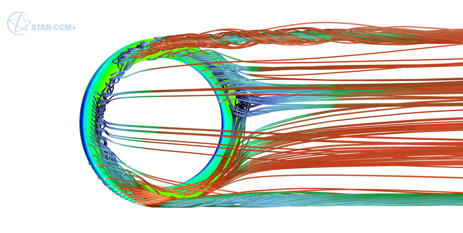 |
| The New FLO 60 Carbon Clincher With a Visual Simulation in STAR-CCM+ |
Why Use an Optimization Algorithm?
In Step 1 and Step 2 of this series we discussed collecting 110,000 real-world wind measurements and analyzing them to find patterns that would help us design faster cycling wheels. Instead of guessing what would be fast by drafting random shapes in software, we wanted to develop an algorithm that used our data to intelligently search for the fastest rims shapes it could find.
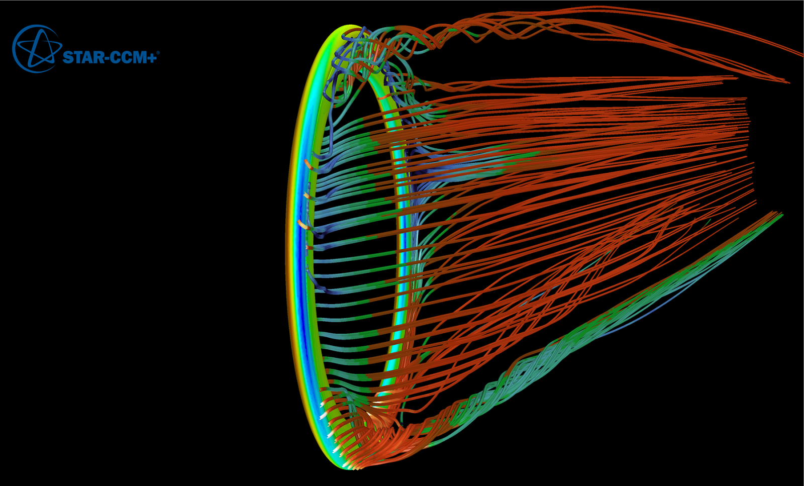 |
| The New FLO 45 Carbon Clincher With a Visual Simulation in STAR-CCM+ |
Creating the Optimization Algorithm
One of the industry’s leading computational fluid dynamics software is CD-adapco’s STAR-CCM+. It’s power and precision is remarkable, and we knew this was our go-to solution for this project. The one downside of this software is that computations can take a long time to complete. The number of calculations required for a project of this size were not possible on a single-processor computer. Knowing this, we decided to work with CD-adapco’s in-house engineering team to help us with this project. Here are some of the benefits of working with their engineering team:
- Access to CD-adapco’s supercomputer, capable of computing solutions at a much faster rate.
- Two Ph.D. computational fluid dynamics engineers working on our project full-time. Both were very well versed in fluid dynamics and operating STAR-CCM+.
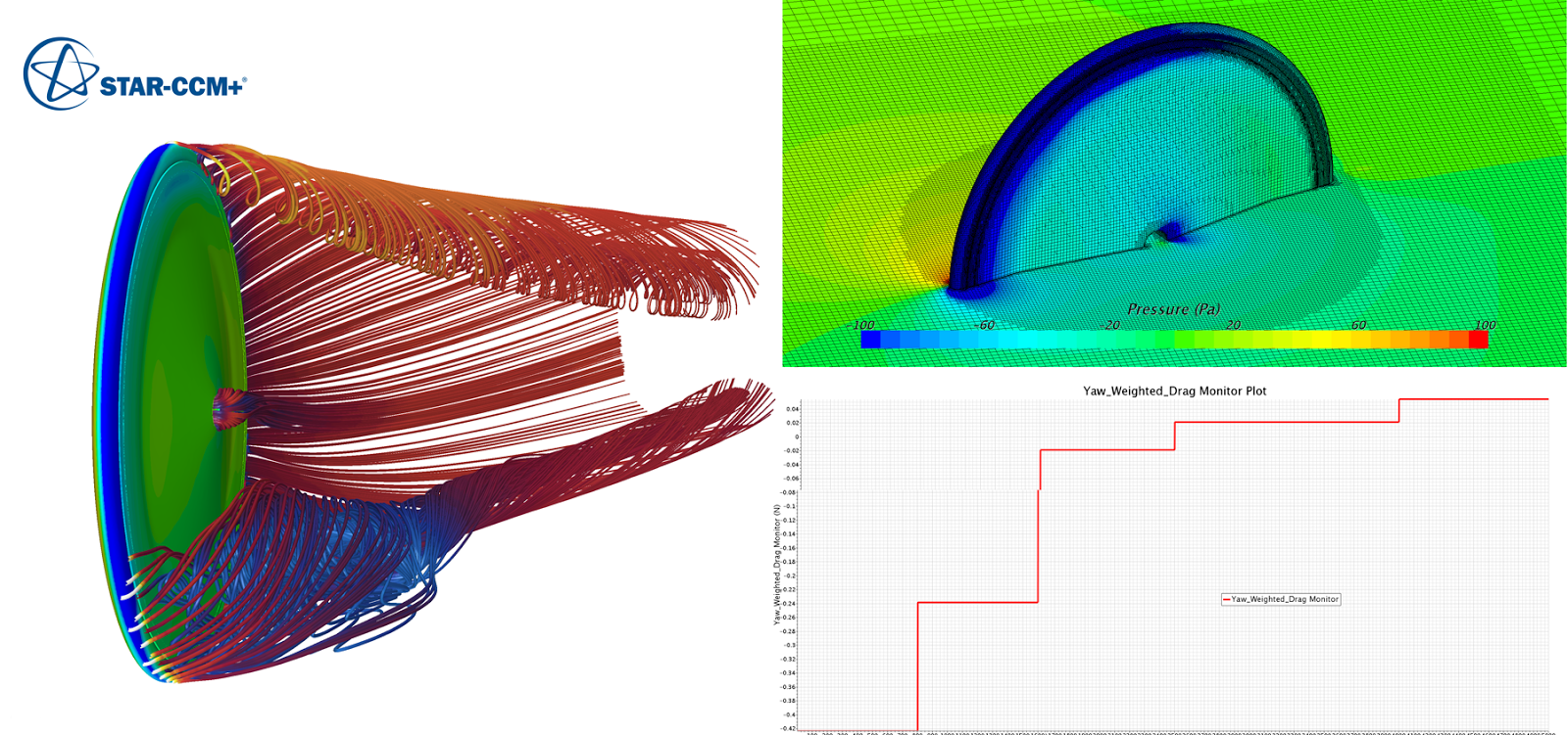 |
| Screen Shot of The New FLO DISC in STAR-CCM+ |
Once we had our team in place, we began developing a parameter set for our algorithm. Each parameter was weighted by importance. Here are the parameters we used to develop our algorithm:
- Our main focus was to reduce aerodynamic drag.
- Crosswind stability was to be maintained or improved from previous models.
- A list of dimensional parameters were set to ensure the wheels would fit on a bike.
- A list of dimensional parameters were set for each depth range designed. As an example, our new FLO 60 should have a depth of anything between 56mm and 65mm.
- A list of dimensional parameters were set to ensure the end product would be manufacturable and functional on a bicycle as a rim.
On top of developing our custom algorithm, we focused on the accuracy of our mesh. The mesh is the number of digital cells that surround your test object. The more cells you have, the better the data you can gather. Knowing that we had the power of CD-adapco’s supercomputer, we spared no expense when developing our mesh. In total we had more than six million cells collecting data for each rim shape we designed, which was roughly three times more than the mesh used while designing our original FLO wheels.
With the algorithm and mesh set, we began running the computations on CD-adapco’s supercomputer. If we had run our calculations on a single-processor computer, the calculations would have taken 1,334 days or 4.5 years to complete. Because we were able to harness the power of CD-adapco’s supercomputer, we completed the calculations in two months. To give you an idea of how big this project was, the design of the original FLO wheels were developed on a single-processor computer in 28 days, or roughly one day on the supercomputer.
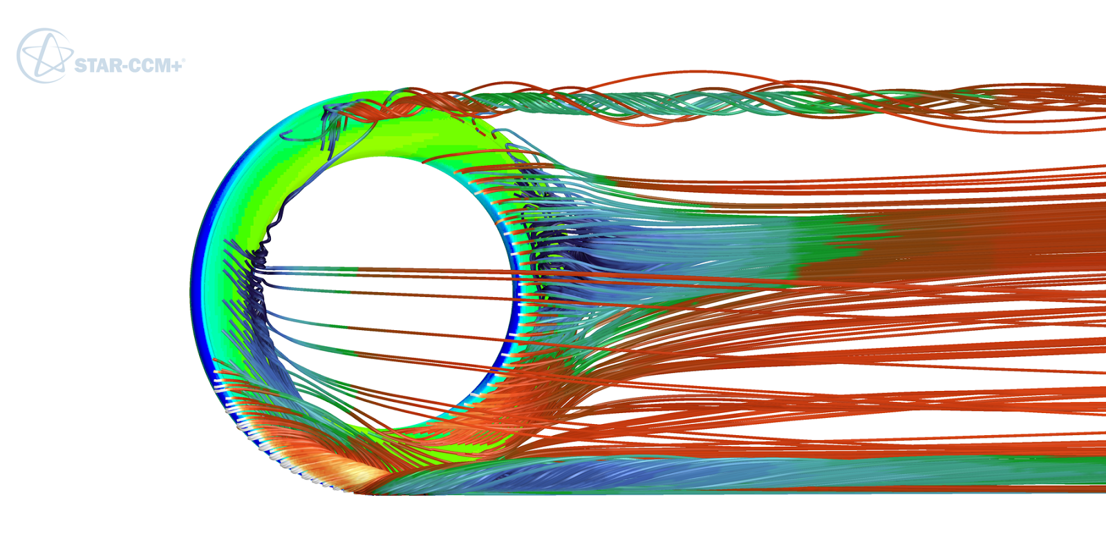 |
| The New FLO 90 Carbon Clincher With Visual Simulation in STAR-CCM+ |
All About The Optimization Process
Our algorithm intelligently iterated through and refined 500 prototypes to find the fastest rim shapes it could. Each design was evaluated at four yaw angles: 2.5, 7.5, 12.5, and 17.5 degrees. For each yaw angle, the geometry was transformed by rotating the wheel and then the model was re-meshed. The solver repeated this 500 times for each design at each angle. The entire process was automated using a Java macro. Each evaluation took two hours to complete on 32 CPUs. Below are the number of modifications made to each rim shape while searching for the fastest shapes, and the number of computing hours used for each rim shape.
 |
| Supercomputer |
Number of Rim Shape Modifications
FLO 45 = 150 Iterations
FLO 60 = 150 Iterations
FLO 90 = 200 Iterations
The FLO DISC uses the FLO 90 profile and was optimized in the design of the FLO 90.
Number of Hours per Wheel Model
FLO 45: 300 hours
FLO 60 : 300 hours
FLO 90 : 400 hours
Our final step was verifying our results in the A2 Wind Tunnel. Be sure to check out Step 5 of this series to read all about it.
Our final step was verifying our results in the A2 Wind Tunnel. Be sure to check out Step 5 of this series to read all about it.
Please let us know if you have any questions about the article. We’d be happy to answer them for you.

Co-founder at FLO Cycling. Jon manages the day to day operations and acts as the lead engineer for all FLO products.