
Legacy Article: The data discussed in this article is taken from our previous generation of wheels.
In 2014 we sat down to redesign our FLO Cycling wheel line. This five-step design process took 15 months to complete and blog series covers the design process in detail. This is Step 3 of our five-step design process. To learn more about Steps 1, 2, 4, and 5, please check out the links below.
Step 3 – 3D Modeling
 |
| Modeling the New FLO Cycling Rim Shapes |
Why is 3-D Modeling Important?
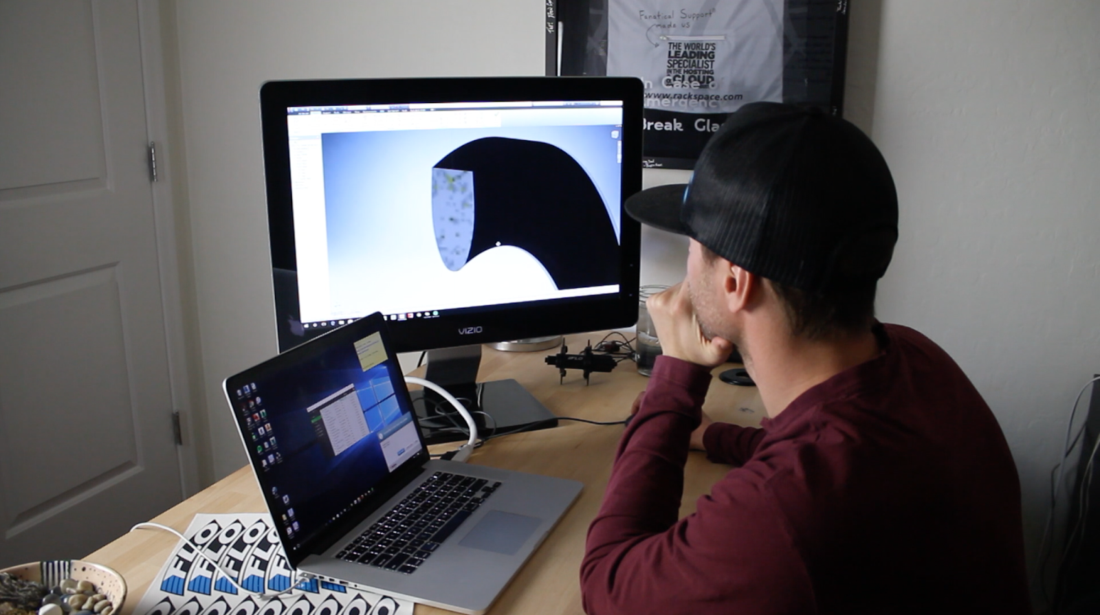
Our goal when designing the 2016 wheel line was to use computational fluid dynamics (CFD) software to help us optimize the process. CFD software is extremely useful and accurate, but it can easily be limited by the quality of the data it’s given. There are two important things to get right when you are setting up CFD software. The first is the virtual environment and mesh that simulates airflow, and completes the calculations. The second is the accuracy of the 3-D model you study in the virtual environment.
For our 2016 wheel designs, we partnered with the talented engineering team at CD-adapco (more on that is in Step 4 of this series). In order for CD-adapco to be able to optimize our new rim shapes, we needed to create the most accurate 3-D models of a wheel and tire we could. Great 3-D models would give us a highly accurate representation of a tire and rim interface, which would translate to a better, real-world product.
How Did We Model a 3-D Shape?
CFD was going to help us optimize the shape of our carbon rims in order to make them as aerodynamic as possible, but one thing that we weren’t going to change was the shape of the tire connected to the rim. Our previous studies have taught us that the Continental GP 4000 S II tire was aerodynamically the fastest tire available, so we decided to base our 3-D tire model on the shape of the GP 4000 S II, in a 23mm size. Another important detail to get right in our 3-D model was the tire and rim interface. The way a tire mates with a rim can have a big impact on aerodynamic performance, so we needed this to be as accurate as possible.
To convert a real-world rim and tire into a 3-D model, we decided to mold a Continental GP 4000 S II tire mounted on a FLO 30 rim. This gave us a 3-D representation of the system that we converted into a 3-D model using Autodesk Inventor.
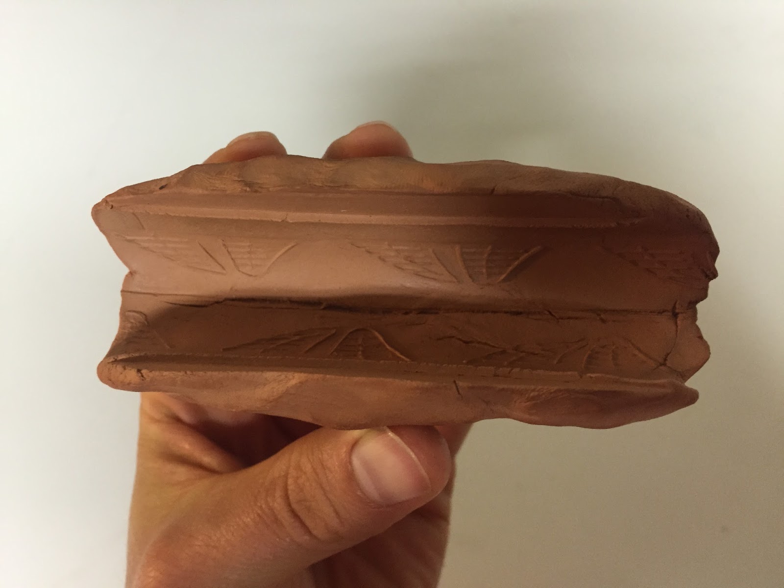 |
| Tire and Rim Mold |
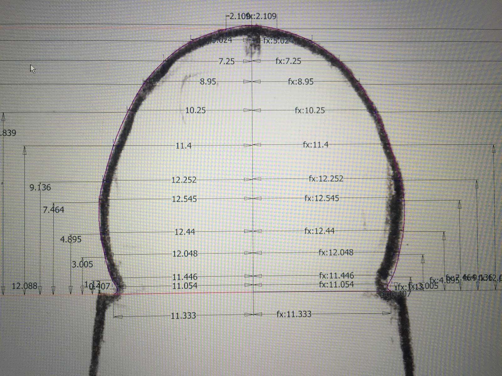 |
| Converting the Mold to a 3-D Model |
Starting the CFD Optimization Process
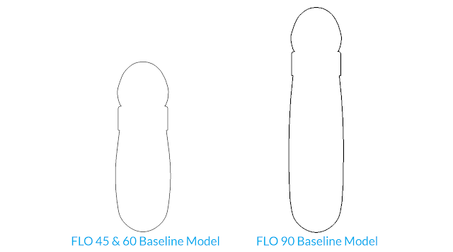
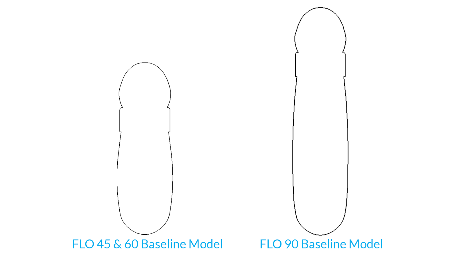
With an accurate 3-D model of a tire mounted to a rim, we were then able to create 3-D model baselines for all of our current cycling wheels. We created 3-D models of the FLO 60, 90, DISC, and a new 45mm depth wheel that we were introducing.
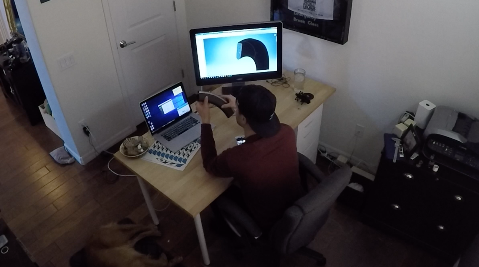 |
| A Normal Day at FLO, Dog Included |
These 3-D models were designed to allow the CFD software to manipulate them in order to search for the fastest rim shapes it could find. We set a list of design parameters (discussed in Step 4 of this series) that allowed the rim shapes and the tire/rim interface to adjust as new models were created. Here are some pictures of the resultant baseline models used for our 2016 wheel design.
With the baseline models complete, it was now time to begin our CFD work discussed in Step 4 of this series.
Please let us know if you have any questions about the article. We’d be happy to answer them for you.
Please let us know if you have any questions about the article. We’d be happy to answer them for you.

Co-founder at FLO Cycling. Jon manages the day to day operations and acts as the lead engineer for all FLO products.