
The wind direction sensor I have been waiting for has finally arrived from Germany. It’s made by a company called Lufft and is accurate to +/- 1 degree. There are a number of wind direction options but most fall into the +/- 5 degree range. Since the yaw angle spread on a bike is narrow, the accuracy is very important.
I also took a look at my old wooden mounting system and noticed the supports had cracked. I decided to replace the support with aluminum. In the process I ended up rebuilding the entire support structure from aluminum and I am happy I did. There are a number of improvements.
Here is a picture of the old mount I had built from wood.
The rest of this blog article shows the building of the mount, the mounting and wiring of each of the sensors, and finally a test of the wind direction sensor.
I used square aluminum stock in 1 inch and 3/4 inch and then 1 1/2 in aluminum flat bar for the build.

I had to make two 90 degree angles for the main support so I used L brackets. While I have a new welder sitting in my garage, I have no idea how to use it yet.

Here is the unit with the two 90-degree sections completed.

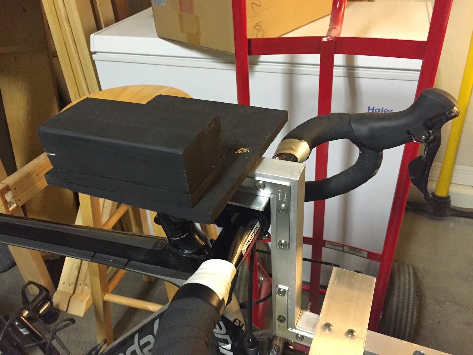
The next step in the process was figuring out how to mount the wind direction sensor. I used the flat bar with a hole drilled in it to hold the sensor. I also used a series of rubber washers to reduce road vibration. In the past I’ve mounted breadboards to the front of the bike for measurements and have quickly realized that the vibration from the road makes resistors bounce around like popcorn. You can see the rubber washers placed under the mount below.

Here you can see the mount bolted to the main support.

The next step was to build a place to mount the batteries that power the wind direction sensor. The wind direction sensor requires 24v so I need a decent-sized battery set up. I placed a piece of flat bar on the main support to house the batteries.

The next step was creating a platform to mount the data logger and some of the sensors. I salvaged part of the old mount for the new one.
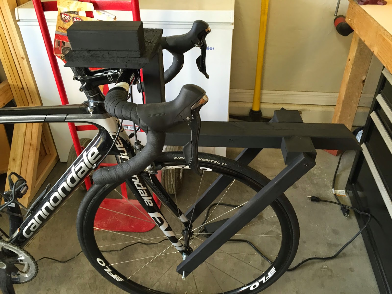
With the basic structure finished I had to create support legs that would mount to the front fork. The idea is that the mount will move with the front wheel since we are studying tires. Below you can see the support members that are holding the mount in place.

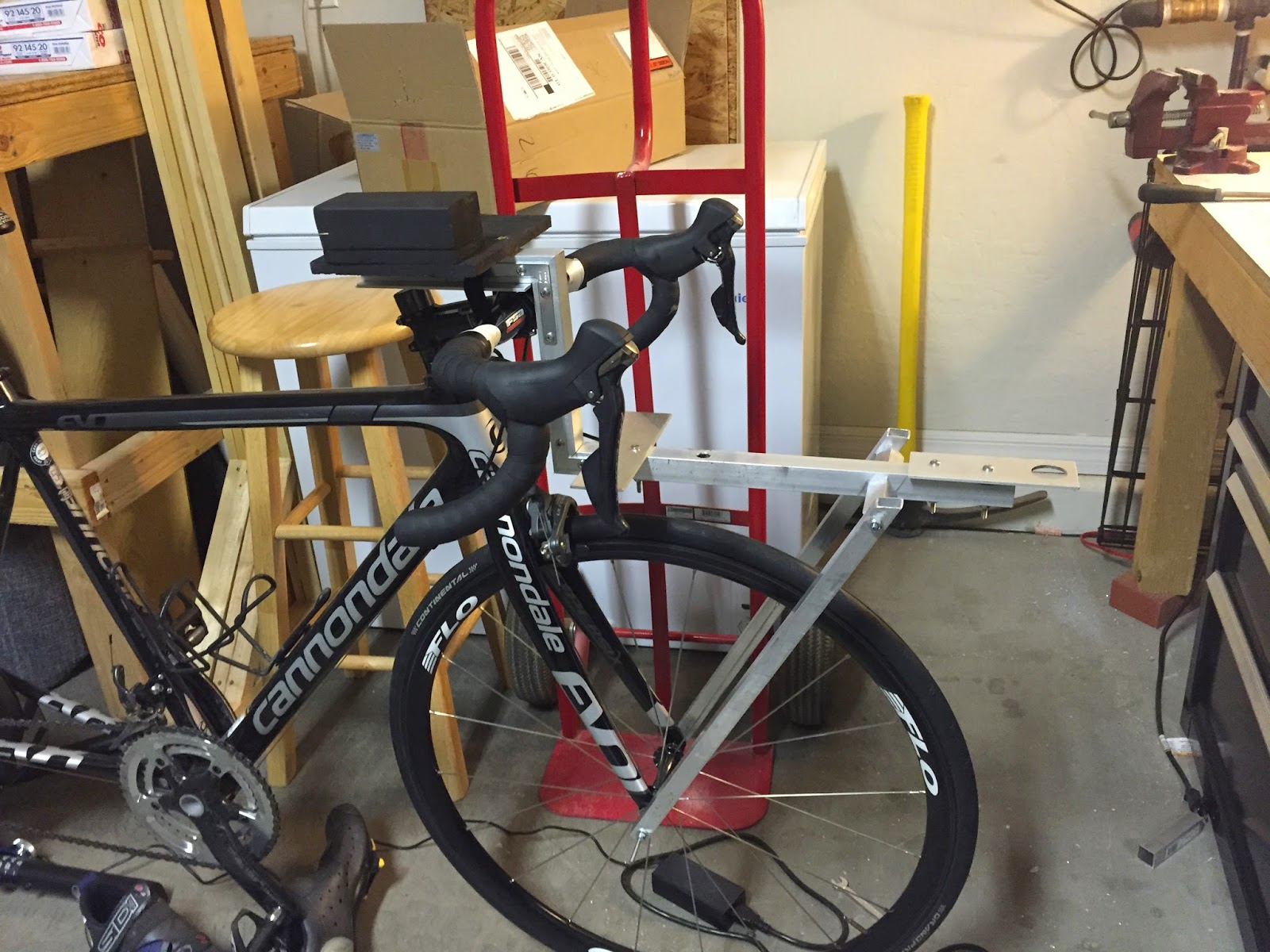
Then I was ready to start mounting the sensors. First up was the wind direction sensor. Below you can see it mounted out front where the air flow will be as clean as possible.

Next up was the wind speed sensor. This was mounted behind and above the wind direction sensor.

The Onset data logger was next. I used a couple of mounting screws to mount the unit above the handle bars. This way I can see if there are any warning lights going off.
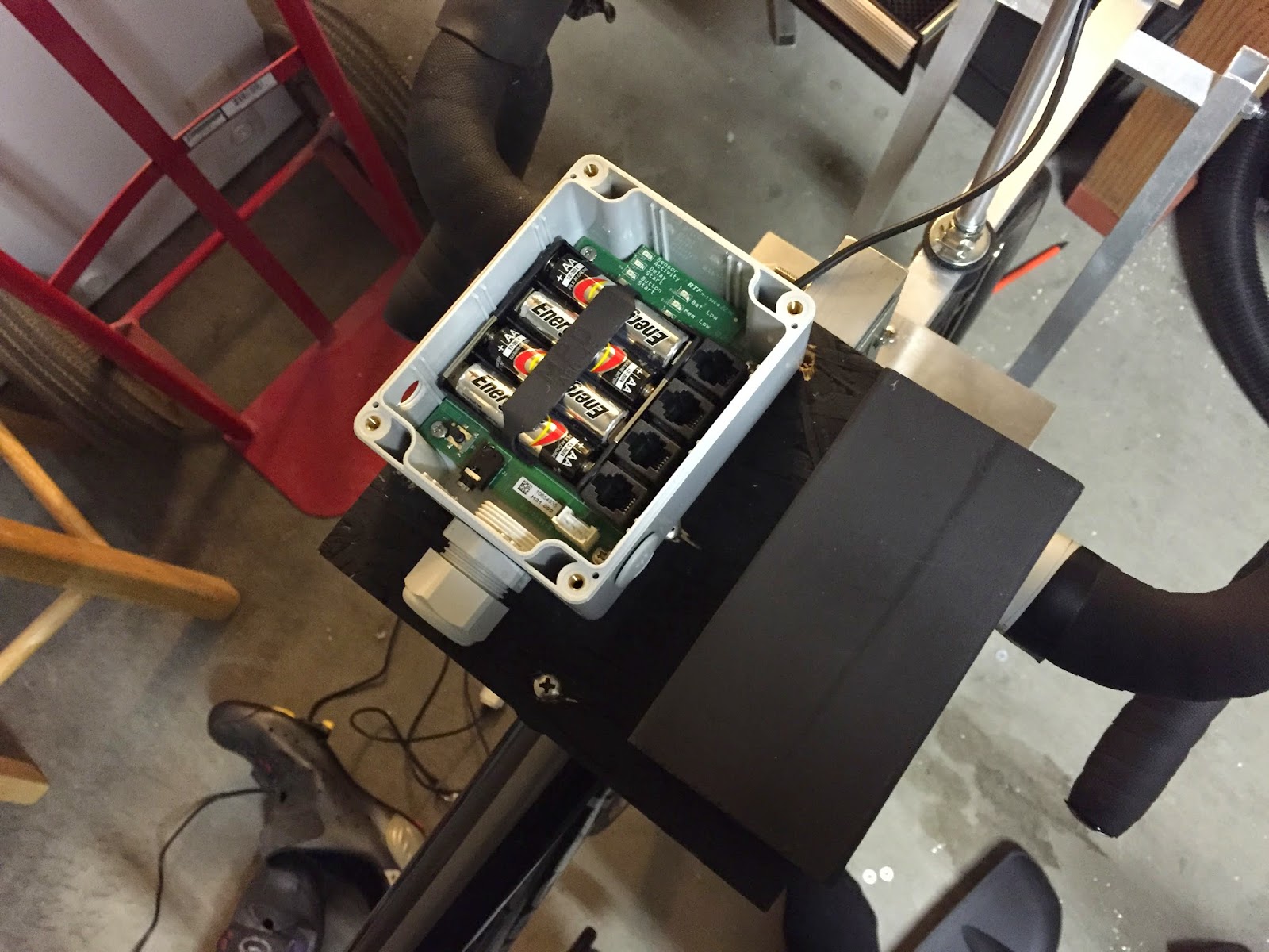
Now to mount the batteries. Yes, that is duct tape. I thought about the best way to mount these and to be honest this was the best way I could think of. The Gorilla tape I used is the toughest tape I’ve ever seen. The batteries aren’t going anywhere.

The wind speed sensor and the temperature sensor came with long cords and some additional hardware. I found an old project box and modified it to hold the cables.
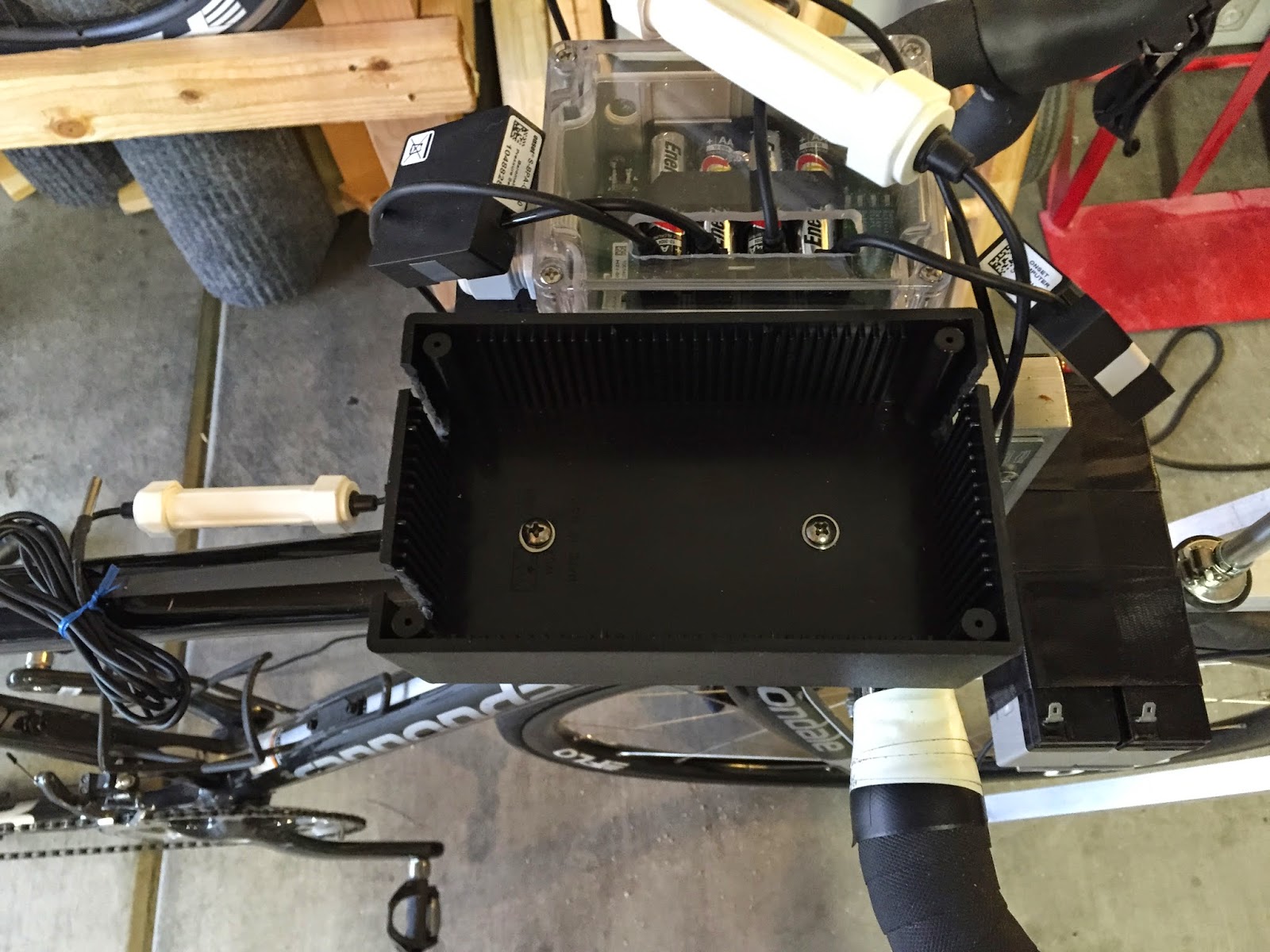
This cleaned up the front of the bike a lot and also gave me a place to enclose the temperature sensor. I wanted to keep it out of the sun to prevent shifts in temperature as I moved in an out of the sunlight.

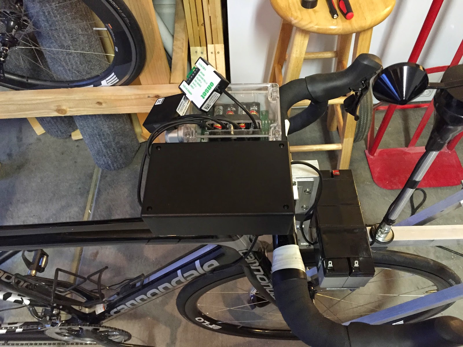
With the cover placed on the box I think you’ll agree things look pretty clean.
The barometric pressure sensor came with a short cable and was housed in a small box. I used double-sided tape to mount this on top of the project box. I also mounted the 4-20mA input on top of the project box. The wind direction sensor has a 4-20mA output and the input receives the info and converts it for storage in the data logger.

The final step was wiring the wind direction sensor to the battery and the 4-20mA input. The first go around I kept the wires a bit long incase there was a problem.

With the wind direction sensor wired up it was time to test it. I had not tested it since it arrived and was really hoping that it would work since I had spent so much time getting everything ready. Luckily for me it did. Below you can see the 4-20mA signal for various angles. When you see the jumps from 4 to 20 this is where the sensor is going from 0-359 or 359-0 degrees. To eliminate this when riding I will end up mounting the sensor so south is pointing forward. This will give me a range centered around 12mA instead of the break at four and 20. While it won’t change the results, the graph will be a little easier on the eyes.

That’s it for today. Now it’s time to get this beast out on the road. For the first couple of days I plan on staying close to home. While I trust my carpentry skills, I am not sure I won’t get chased off the road for being the biggest nerd in Las Vegas =].

Co-founder at FLO Cycling. Jon manages the day to day operations and acts as the lead engineer for all FLO products.