
Updated: 12/30/2022
Deep carbon fiber cycling wheels are faster due to better aerodynamics. While that’s a known fact understanding why they are faster is something most people do not understand. In fact, the right wheel, in the right situation can actually act like a sail and propel you forward. Yes, you heard that right, a good cycling wheel can give you thrust (forward motion for free) instead of drag (a force that holds you back). The aero wheel tutorial below will walk you through everything you need to know about cycling wheel aerodynamics. To get started, let’s define some terms.
Term 1: Yaw Angle
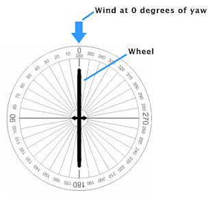
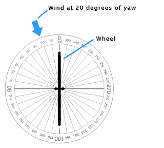
A yaw angle is the angle at which the wind interacts with the wheel. In Figure A, the wind (blue arrow) is hitting the wheel at 0 degrees. This is known as 0 degrees of yaw and you would say the yaw angle is 0. In Figure B, the wind is now interacting with the wheel at a 20-degree angle. This is known as 20 degrees of yaw and you would say the yaw angle is 20 degrees.
Term 2: Head Wind
Head wind is the component of the wind that hits you in the face. A pure head wind would be when the yaw angle was 0 degrees.
Term 3: Tail Wind
Tail wind is the opposite of head wind. Instead of the wind hitting you in the face it would hit you in the back of the head. A pure tail wind would be when the yaw angle was 180 degrees.
Term 3: Side Wind
Side wind is the component of the wind the hits you in the ear. A pure side wind would be when the yaw angle was +/- 90 degrees. The +/- means either your left side or right side. For example +90 degrees could be your right side and -90 degrees would be your left side.
What a Cyclist Experiences
It would be exceptionally rare for a cyclist to experience a pure head wind (0 degrees of yaw), a pure side wind (+/- 90 degrees of yaw), or a pure tail wind (180 degrees of yaw). In fact 99.99% of the time a cyclist is experiencing a combination of head wind and side wind or tail wind and side wind. In all of our examples below we use the more common case of a combination of head wind and side wind. This is where a well design cycling wheel shines when it comes to aerodynamics. To learn more about the exact angles a cyclists see check out our yaw angle data models taken from more than 100,000 data points we collected.
If you have any background in mathematics you will start to see that cycling wheel aerodynamics is all out vector math. If this sound like greek to you hang tight. We will explain everything in detail below.
The Leading Edges of a Cycling Wheel
Water like air is a fluid. The advantage of water is that you can see it move. To help our understanding, we will use water to help our understanding.
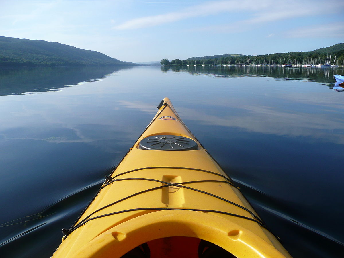
Picture of a canoe moving through a calm lake. The front of the canoe is the first part of the boat to cut through the water. It is therefore defined as the “leading edge.” When the canoe moves through the water the front of the canoe collides with water molecules that make contact with the leading edge. Those water molecules then push into the water molecules in front of them. These collection of collisions builds pressure in the water at the front of the canoe which eventually moves around both sides of the canoe. What you end up seeing is ripples in the water that move along the sides of the canoe. See Figure C below. A cycling wheel in the wind is no different. The only difference is the fluid. In the cycling wheel case the wheel moves through air not water.
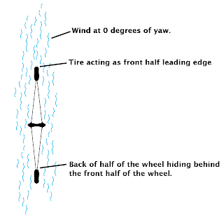
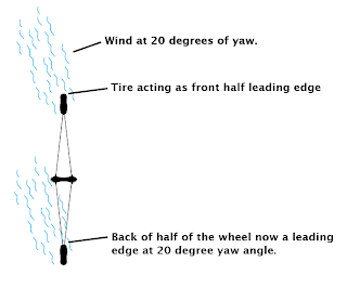
A wheel can have two leading edges. The first is the tire at the front of the wheel, and the second is the carbon fiber fairing at the back of the wheel. When a wheel is at 0 degrees of yaw, the front of the wheel is the only leading edge. This is because the back of the wheel is “hiding” behind the front of the wheel (see Figure D). When a yaw angle of greater than 0 degrees is introduced, we now have two leading edges. Figure E shows the wind at 20 degrees of yaw. The back of the wheel can no longer “hide” behind the front of the wheel and sees its own air. Therefore the wheel now has a second leading edge.
Aerodynamic Forces on a Cycling Wheel
Drag
Drag is defined as the force on an object that resists its motion through a fluid. If you stand in waist deep water and try to run forward, the force you feel holding you back is drag. Air also has drag, just not as much as water since it has a lower viscosity.
Side Force (Lift in Planes)
Side force is one of the most important forces to consider when designing aerodynamic cycling wheels. Side force is the same force as lift in an airplane with the only difference being the force acts on the side of a wheel instead of underneath a wing. Let’s explain lift in an airplane wing to get a better understanding of side force in a cycling wheel.
The wings of an airplane allow it to fly, but how? To answer this, let’s look at the forces acting on an airplane (see Figure F). Thrust is the force generated by the engine of the airplane to move it forward. Drag is the force exerted by the air that resists the forward motion of the airplane. Let’s ignore these two forces for now.
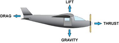
Gravity is the earth’s attractive force that wants to keep the airplane on the ground. Lift is the force we need to create in order to get the plane off the ground. To take flight, we need the lift force to be greater than the gravitational force. Lift is generated by the wing. A wing has three major components that contribute to the lift force it produces. Those three components are:
- The shape of the wing.
- The wing’s angle of attack.
- The velocity or speed of the wing.
The shape controls the way the air (fluid) moves around the wing. By controlling the airflow, we can create areas of high pressure below the wing, and areas of low pressure above the wing. Any time there is a difference in pressure on opposite sides of an object, the high pressure side pushes the object towards the low pressure side. A simple example is blowing on one side of a ballon inflated with helium. The side you blow on creates a high pressure zone so the ballon moves away from your toward the low pressure side at the back of the ballon opposite your breath. When the pressure under the wing is high enough to overcome the gravitational force, the plane will lift off of the ground and fly.
The angle of attack is the angle that the wing moves through the air. This is the same as the yaw angle of a wheel. As you increase the angle of attack, you increase the lift force until you reach the critical angle of attack. The critical angle of attack is the angle that produces the maximum lift. After this critical angle the wind stalls and the lift force drops off quickly. Think of sticking your hand out of the window of a moving car. By turning your hand up or down (changing the angle of attack), you can make your hand rise or fall. If you turn your hand too far in either direction, it no longer moves up but moves backwards and down.
Finally we have the velocity or speed at which the wing travels through the air. The simple answer here is, the faster you go, the more lift you create.
How To Make a Cycling Wheel Aerodynamic
When designing aerodynamic cycling wheels we consider two things. The first point is the reduction of drag. In order to be fast, the wheel must reduce aerodynamic drag as much as possible. The second point is the stability of a wheel in a side wind (aka cross wind). Anyone who has ridden deep wheels in a strong side wind knows they can be a challenge to control. Therefore, it is important to design a wheel that has good cross wind stability. To learn how we design for low drag and cross wind stability check out our optimization algorithm.
Side Force
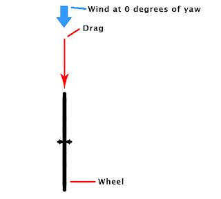
In order to reduce the drag in a cycling wheel we need side force. Figure G shows a wheel at 0 degrees of yaw. When you are in 0 degrees of yaw the side force is 0 since the air flows evenly around both sides of the wheel. Luckily for us, we know the cyclist nearly never sees a yaw angle of 0.
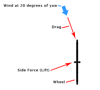
As soon as we introduce a yaw angle greater than zero degrees but less than +/- 90 degrees we create side force. The yaw angle is that same as the angle of attack in an airplane wing. Figure H shows a wheel at 20 degrees of yaw. This produces a higher side force on the side of the wheel facing the wind and produces side force. Note: The arrows represent vectors. While it may appear strange that the side force vector is at the angle shown, know that the side force is alway perpendicular to the drag force. The reasons are beyond the scope of this blog.
Let’s now consider the side forces that a non aero wheel like a standard training wheel experiences. Because a standard training wheel has very little rim depth, it generates very small side force. For sake of argument, the drag is more or less equal to the side force. An aero wheel however, has a much deeper rim profile and an increased surface area. The increased surface area generates a higher drag force but it also creates a much larger side force. The ratio moves away from 1:1 like that seen in a training wheel. The key is to design a fairing shape that produces the largest percentage of side force relative to drag while maintaining wheel stability in cross wind.
Cycling Wheel Vector Math
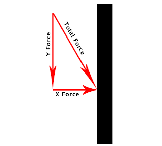
When a force pushes on a surface at an angle (like a yaw angle), a portion of that force pushes the object in the X direction and a portion of that force pushes the object in the Y direction. Take a look at Figure I.
Understanding vectors take a look at Figure J which shows the vectors of drag and side force as they act upon a cycling wheel.
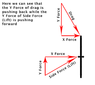
What is important to note is that the Y component of side force actually opposes the Y component of drag. This is the key to designing an aerodynamic cycling wheel and why in the right case you can create thrust. When the Y component of side force is greater than the Y component of drag you create forward motion (thrust). However, we do not need thrust to create an aerodynamic cycling wheel. Any reduction in drag results in a win and creates a faster wheel. Let’s take a look at two numerical examples to show how this work out mathematically.
Calculating Drag Force On Cycling Wheels
Let’s consider a the following.
Example 1 – Training Wheel
Drag Force – 100g
Side Force – 100g
Yaw Angle – 5 Degrees
Therefore:
Drag Force Y-Component = cos(5 degrees) * 100g = 99.62g
Side Force Y-Component = sin(5 degrees) * 100g = 8.71g
Resultant Drag Force = (Drag Force Y-Component) – (Side Force Y-Component)
Resultant Drag Force = 99.62g – 8.71g
Resultant Drag Force = 90.91g
Example 2 – Aerodynamic Wheel
Drag Force – 150g
Side Force – 800g
Yaw Angle – 5 Degrees
Therefore:
Drag Force Y-Component = cos(5 degrees) * 150g = 149.43g
Side Force Y-Component = sin(5 degrees) * 800g = 69.72g
Resultant Drag Force = (Drag Force Y-Component) – (Side Force Y-Component)
Resultant Drag Force = 149.43g – 69.72g
Resultant Drag Force = 79.71g
As you can see from the above two example, the aerodynamic wheel has a lower resultant drag even though the drag for is higher. When the rim shape is designed effectively you can greatly reduce the resultant drag in wheel and keep it stable. It’s exactly what our optimization algorithm does. We first used it to design the wheels release din 2016 and it was also used to design our All Sport and Gravel wheels. If you in the market for new wheels please take a look and let us know if you have any questions.

Co-founder at FLO Cycling. Jon manages the day to day operations and acts as the lead engineer for all FLO products.